|
|
||
 |
|
|
|
|
||
|
|
||
|
|
||
|
|
||
|
|
||
|
|
||
|
|
||
|
|
|
|
|
|
||
| PDF - BeamSonics v2.0. Component layout and tracks |
|
|
|
|
||
| BEAM Sonics is a clever little circuit designed by Wilf Rigter. It's central function is to filter incoming sounds and count high pitched pulses, whistles, beeps etc. When it hears a certain number of beeps it will respond with a noise of its own. If left on its own it will ocasionally produce a beep anyway, just to see what else is out there. WIlfs complete description of how it works can be found at the bottom of the page.
After building several sonics circuits for a project I decided to rework it into a more flexable design with added features, as suggested by Wilf. The new design allows for a variety of inputs. As well as an electret mic so you can use light sensors, it also incorporates an alternative output stage to the standard piezo sounder that will drive a coil or other inductive load. |
|
|
|
|
 |
|
|
|
|
|
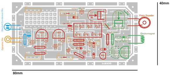
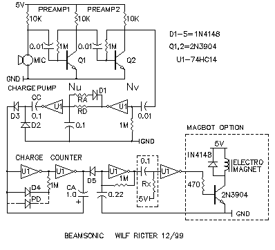
This PCB allows for several inputs and outputs with the relevant components marked in different colours. Red is for standard parts and a piezo output, Green for a coil driver output, Yellow for dynamic mic input and Blue for an electret mic input. The yellow dotted oblong and square markings are for PCB Strip sockets or PCB pins. Space is provided for two preset pots that control the output oscillator frequency (Pitch) and the output pulse duration for the coil driver option. For Wilfs schematics and an explanation of how it works see the bottom of the page.
|
|
|
|
|
 |
|
|
|
|
 |
Scroll down for his explanation of how it works |
|
|
|
 |
|
|
|
|
|
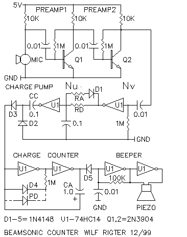
The SONIC circuit is a sound processor which generates a chirp if it receives several chirps (or other sound packets) from external sources like other chirpers or human whistles. It's function is based on a concept by Bruce Robinson and it is one of those projects that is looking for a "killer application". In the mean time this article is presented here for your enjoyment, for discussion and a test platform of related ideas eg adding sound sensing and sound processing to a beam bot. The project combines several typical BEAM subsystems and components which have been used for many other applications. The circuit uses a single 74HC14 available from Solarbotics, etc. and a handful of other parts readily available from Radio Shack making it easy to get started. Unlike the SMART HEAD which required careful fine tuning to get results, the SONIC circuit component values are not particularly critical and you may substitute or adjust values to suit. This will change some circuit parameters but nothing's going to "hang up" and cause frustration. As shown in the attached schematic, a electret microphone signal is increased by a factor of about 2000 with two AC coupled transistor amplifiers (Q1-2). The small coupling capacitors provide a high pass filter function which strips off any low frequency "rumble" sound and vibration which could cause problems for example on a moving robot. MICROPHONE AMPLIFIER The microphone amplifier is a sound receiver, sensitive enough to pick up a low level sound, ie chirper/beeper, 5 or 6 ft away. Clapping your hands or whistling can be easily be detected 15 or 20ft away. When the microphone detects a chirp or a whistle, the pre-amp output is a complex sound waveform with a mix of analog and clipped signals. This output signal is large enough to drive the following level detector stage. SOUND LEVEL DETECTOR The next section of the SONIC circuit uses a AC coupled Schmitt trigger (Nv neuron) as a threshold detector which processes the amplitude information of the incoming sound. Triggered by any sound pulse with an envelop above a minimum level, the Nv output is a clipped digital waveform with a duration and frequency of the incoming sound pulse. SOUND DURATION DETECTOR The following Nu neuron stage is a dual time constant integrator which sets a threshold for the minimum duration of and the minimum delay between sound pulses. The Nu filters clicks and noise pulses shorter than 10ms from the incoming sound. The Nu stage produces a single positive output pulse which is at least 10ms and as long as the duration of the incoming sound pulse. Resistor RA, in series with diode D1 and in parallel with resistor RD, sets the Nu "attack" time ie the minimum required input pulse duration. The parallel resistor RD sets the Nu "decay" time which determines the minimum Nu output pulse duration and therefore the minimum delay between incoming sound pulses. Values of RA and RD are nominally 100K. In general, RA is equal or smaller than RD but values can be adjusted to suit. HARGE PUMP The following charge pump (diode dump) circuit uses the positive edge of the Nu output pulse to transfer a single charge on the charge capacitor (CC) through D3. The charge on CC is reset on the negative edge of the Nu output pulse through D2. This way discrete pulses are transferred on the rising Nu output which can be counted by the following charge counter. ANALOG COUNTER The analog charge counter ciruit is closely related to the classic CMOS oscillator. It is used to accumulate discrete charges from the charge pump on capacitor CA until the voltage on CA crosses the input trigger level of the Schmitt trigger. When that happens the counter circuit output rapidly changes to the active state, and just like a standard CMOS oscillator, uses positive feedback from the non-inverting output to dump the charge on CA through the 74HC14 input protection diodes. Next CA start to rapidly charge in the reverse direction through D4 and the 1M resistor with negative feedback from the invering output. When the voltage on CA crosses the lower trigger level, the active outputs are terminated and the charge on CA is again dumped through the 74HC14 input diodes and the counter is "reset" (CA charge is zero). The number of charges required to trigger the charge counter is set by the ratio of the charge cap CC (0.1uF) and the accumulator cap (CA (1.0uF) as well as the Schmitt input threshold. In this SONIC circuit, that number is arbitrarily set to 6 which makes the circuit act as a divide by 6 counter, generating one output pulse for every six input pulses. The counter divider ratio can be adjusted by changing the ratio of the two capacitor values. The charge counter active output pulse duration is set by the 1M resistor which can be changed to other values if required. COUNTER MODULATING The optional PD is a green LED or photodiode which provides a reverse bias leakage current to charge capacitor CA causing the counter to dynamically change divider ratio (modulus) with time and light level requiring fewer pulses to trigger in brighter light. This tends to make SONIC circuits more active in brighter light. If used on bots this may be also used to influence group behaviour since the frequency of chirps in a group will increase exponentially with group size and light level. SOUND TRANSMITTER The beeper circuit is a conventional gated Schmitt trigger oscillator plus inverting buffer with a piezo element driven by the push-pull outputs at an equivalent 10Vpp signal level. The RC components may be adjusted to set the oscillator frequency to the piezo resonant frequency to maximize the sound volume. APPLICATIONS The charge counter generates complementary outputs used here to echo a sound chirp after hearing six incoming chirps but which can be used for many other things like halting or reversing a bot . With the PD installed, at low light level and with no input sound pulses, the charge counter self-generates a chirp after a relatively long time. (Who says you can't divide by zero!) In bright light the SONIC circuit self-generates chirps more frequently and triggers after fewer input sound pulses making the circuit more active and contributing more to communal chirping. In a colony of chirpers, SONIC transmitters could be tuned to notes of the musical scale. I would expect some unusual emergent sounds to occur including the sponaneous generation of BEAM MUSIC (which perhaps only a Beamer could enjoy). As I write this, the SONIC project is breadboarded on a workbench 20 ft away and with a couple of short whistles I get a nice "I'm alright, you're alright" chirp in response, so I know it's safe for me to recommend you build this circuit yourself and end the silence of the bots ..... enjoy! wilf |
|